Latest

Kyubu 2.0

Kyubu 2.0 is a highly functional top hat wearing robot that will avoid obstacles and go to people he likes. Kyubu 2.0 is the most fearsome Kyubu of all!!


img_0312-2

img_03121

Initially We had an Idea to Have a Flying Kyubu but He is too fat and square to fly so we thought wheels to be an easier method.

img_0251


Bills of Materials:

  • 2 parallax continuous servos
  • 2 peanut butter lids(used for the wheels)
  • lego pieces(used for third wheel and easy access to kyubu’s organs)
  • 2 squared block of wood
  • jumper wires
  • Arduino UNO
  • breadboard
  • capacitors
  • 9v batteries
  • battery snap
  • Styrofoam cardboard(to build Kyubu)
  • drill
  • hot glue gun
  • screws
  • acrylic paint
  • duct tape
  • soldering iron
  • sensor:Ultrasonic Range Finder (model:MB1043)


some sets for male header pins to put into the servos so you can attach it to the breadboard

Optional third wheel: Legos (We used a Lego wheel and some lego pieces)


DSC_0880IMG_0423We bought 2 Styrofoam boards from the nearest dollar store and began cutting 6 sides. We used 2 so we can have 2 covers, one being brought where ever and the other being the more presentable backup. My partner and I began cutting the pieces.  We also needed a permanent bottom so that all we needed to do to change bodies was remove the top. The permanent bottom would contain all the circuits.12

This was our nonworking model of Señor Kyubu. We added a mustache and called it Señor Kyubu but then I removed the mustache because it didn’t look right on the final model so we went back to the first name Kyubu 2.0

5


IMG_0411WIMG_0412e then began on the Wheels. We used peanut butter caps and added wood inside the caps so it will be more sturdy. We added screws to insure that the peanut butter cap and the wood is well mended together. Then we used 2 parallax 360 continuous servos and hot glued them to each cap.

  IMG_0410


IMG_0389IMG_0461
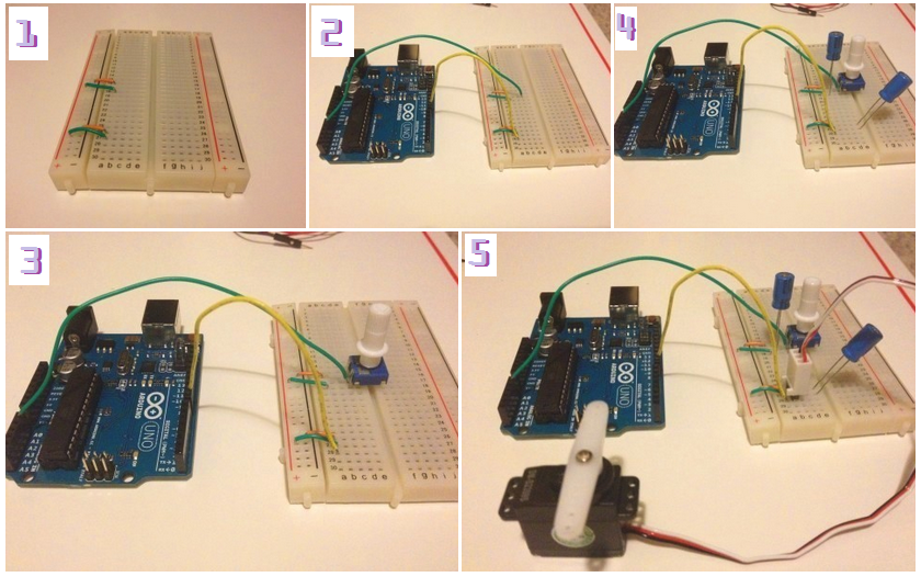
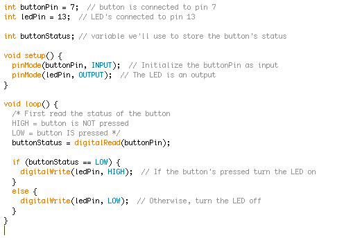
We began plugging the 2 servos into the breadboard and Arduino. The Arduino Uno board itself and the wheels were being powered by 2 9V batteries. My partner and I successfully have gotten the wheels to work using the code below


DSC_0873

IMG_0462

We ran into many problems that we were trying to figure out for more that 24 hrs. Using the sensors and attaching it to the wheels was the hardest part. We were first using the IR sensor but that was getting us nowhere so we changed to the Ultrasonic Range Finder. Even switching to another sensors, we used various methods but sadly we could not get the sensor to work with the wheels. We researched online to see what we could do and saw many examples that other people did too but it did not seem to work. We also went on the Arduino.cc site and checked out the libraries and learning sections, references too but could not find a solution. We also checked ou the Arduino forum but still could not find a clear answer. At this point we did not even know where to look and was hoping that someone divine could help us or lead us to the direction that we will find our answer but we didn’t. We also went to a Professor for help but the most he said is to check the circuit and the problem can lie on the circuit but my partner and I know it wasn’t. The circuit was fine but the sensor was being a jerk.


Final Code (that works!!!):

#include <Servo.h>
const int numReadings = 5;
int readings[numReadings];
int idex = 0;
int total = 0;
int average = 0;
Servo leftMotor;
Servo rightMotor;
const int anPin = A0;
long  mm, inches;

void setup ()
{
Serial.begin(9600);
leftMotor.attach(9);
rightMotor.attach(3);
for( int thisReading = 0; thisReading < numReadings; thisReading++)
{
readings[thisReading] = 0;
}
}
void read_sensor (){
average = analogRead(anPin);
mm = average*5;      //Takes bit count and converts it to mm
inches = mm/25.4;   //Takes mm and converts it to inches
}
void print_range ()
{
Serial.print(“S1”);
Serial.print(“=”);
Serial.print(mm);
Serial.print(” “);
Serial.println(inches);
}

void loop ()
{
read_sensor();
total = total – readings[idex];
readings[idex] = analogRead(anPin);
total = total + readings[idex];
idex = idex + 1;
if (idex >= numReadings)
idex = 0;
average = total / numReadings;
print_range();
delay(200);
if(inches < 15)
{
leftMotor.write(-90);//backwards
rightMotor.write(180);
delay(1000);
leftMotor.write(-10);
rightMotor.write(200);
delay(1000);
}
else
{
leftMotor.write(180); //forward
rightMotor.write(80);
}
}

meowmeowmeow

Kyubu VERSION 2.0!!!!

What What!?

Kyubu on Wheels!? This is blasphemy! Now that Kyubu may come in wheels! He can obliterate us all with his super sonic attack!! WHAT WHAT!? Whats this!? He is coming back with more fire power?? AAAnnndd a Top Hat?? Beware people! Kyubu is coming back more bad tush(substitute for the a-word) than ever !!IMG_0251Originally I wanted a flying Kyubu…

IMG_0312 2

But he is too fat and square to fly… SO! we give him wheels 🙂

 IMG_0312

Project 4 – Color Mixing Lamp

The code that was used:

const int greenLEDPin=9;
const int redLEDPin=11;
const int blueLEDPin= 10;
const int redSensorPin=A0;
const int greenSensorPin=A1;
const int blueSensorPin=A2;
int redValue=0;
int greenValue=0;
int blueValue=0;
int redSensorValue=0;
int greenSensorValue=0;
int blueSensorValue=0;
void setup(){
Serial.begin(9600);
pinMode(greenLEDPin,OUTPUT);
pinMode(redLEDPin,OUTPUT);
pinMode(blueLEDPin,OUTPUT);
}
void loop(){
redSensorValue=analogRead(redSensorPin);
delay(5);
greenSensorValue=analogRead(greenSensorPin);
delay(5);
blueSensorValue=analogRead(blueSensorPin);
Serial.print(“Raw Sensor Values \t Red: “);
Serial.print(redSensorValue);
Serial.print(“\t Green: “);
Serial.print(greenSensorValue);
Serial.print(“\t Blue: “);
Serial.println(blueSensorValue);
redValue=redSensorValue/4;
greenValue=greenSensorValue/4;
blueValue=blueSensorValue/4;
Serial.print(“Mapped Sensor Values \t Red: “);
Serial.print(redValue);
Serial.print(“\t Green: “);
Serial.print(greenValue);
Serial.print(“\t Blue: “);
Serial.print(blueValue);
analogWrite(redLEDPin, redValue);
analogWrite(greenLEDPin, greenValue);
analogWrite(blueLEDPin, blueValue);
}

Project 5 – Mood Cue

Purpose – Mood Cue points out what sort of mood you’re in that day.

Bill of Materials:

IMG_0084

Code that was used:

#include <Servo.h>
Servo TheServoMotorStuff;
int const potatopin=A0;
int potatopinValue;
int themoveymoveypart;
void setup(){
TheServoMotorStuff.attach(9);
Serial.begin(9600);
}
void loop(){
potatopinValue=analogRead(potatopin);
Serial.print(“potatopinValue: “);
Serial.print(potatopinValue);
themoveymoveypart=map(potatopinValue, 0, 1023,0,179);
Serial.print(“, themoveymoveypart: “);
Serial.println(themoveymoveypart);
TheServoMotorStuff.write(themoveymoveypart);
delay(19);
}

First Screw in the Motor Arm into the Servo Motor.           1

Then break of 3 pieces of the male header pins and attach it to the servo motor wires so it can smoothly connect to the bread board.2

First connect the  short Jumper Wires, then the longer jumper wires. Afterwords attach the potentiometer. The potentiometer is a variable resistor with three pins. the middle pin that is known as the wiper, moves across the resistor dividing it into two halves. The external sides of the potentiometer are connected to the ground and voltage. At this time when attaching, an error occurred. The pins would not go into the breadboard the way the Arduino booklet view it and I did not want to break the piece so I tried my best to place it in so it would not break. Afterwards I added the capacitors. As we all know, capacitors store and release electrical energy in a circuit. Once the two capacitors were placed, I finally connected the servo motor. The servo motor is a type of gear that can only rotate 180 degrees and is controlled by sending electrical pulses from the Arduino. The pulses from the Arduino tells the Motor Arm what position it should move. 3

IMG_0095

The code was uploaded successfully but it would not function. The reason why is most likely because of the placement of the Potentiometer.

IMG_0096


(〜 ̄▽ ̄)〜Part 2 – Quiz (\(〠_〠(\)

1.) What is Arduino?

An Arduino is micro controller development board in which you can write a software for the board, create a code to put in.

2.) What is electricity? Current? Voltage? Resistance?

Electricity is a form of energy.

A current  is an amount of charge that flows past a specific point during a time interval.

Voltage is a potential difference that is resulted from the distribution of charge in the circuit.

Resistance goes against a substance that offers the flow of current energy.

3.) What is a circuit? How does electricity flow in a circuit?

A circuit is a path between two or more points, electrical current is carried through the circuit. The electrical current travels from positive to negative.

4) What is Ohm’s law? When might you use it? How would you use it?

Ohm’s law tells us that current, voltage, and resistance are related and that if one is changed then that effects the others. When you measure amperage in the circuits, you’ll also be building values.

5.) What is a series circuit? Parallel circuit?

A series circuit is a circuit that has resistors that are arranged in a chain so the current can take only one path.

A parallel circuit has two or more paths that there is current to flow through.

6.) What is the difference between digital and analog signal/voltage? Describe an example.

Analog signal represents physical measurement. Examples – Video and audio transmissions are often transferred or recorded using analog signals.

Digital signals are an finite set of possible values. Examples – Not all audio and video signals are analog. Standardized signals like HDMI for video (and audio) are all digitally transmitted.


7.) What is code?

Programmed instruction or system of words, letters or symbols.

8.) What is a variable? How is it used in Arduino?

A variable is a place to store a piece of data. It has a name, a value, and a type.

In the Arduino it is used like this int pin = 3

9.) What is a function? How is it used in Arduino?

A function segments code into functions that allows a programmer to create modular pieces of code that perform a defined task and then return to the area of code from which the function was “called”.

10.) What two functions are required in Arduino code? What do they do?

The two functions that are required are setup() and loop(). setup() is the start of the sketch and loop() is the consecutive and controls the Arduino.

11.) Write one function that sets the pins on an Arduino.

int ledPin = 6;

void setup()

{

}

void loop()

{

digitalWrite(ledPin, HIGH);   // sets the LED on

delay(100);                  // waits for a second

digitalWrite(ledPin, LOW);    // sets the LED off

delay(100);                  // waits for a second

}


12.) How do you end a statement in Arduino?

You end a statement with a curly brace.

13.) What are curly braces/brackets used for in Arduino?

To start and end statements.

14.) Describe one digital function and one analog function.

Digital function would be PinMode which makes something behave as an in or output. An analog function configures the voltage used for analog input.

15.) What are conditional statements in Arduino? Name one and describe its use.

 if is a conditional statement. and example would be :

if (switchState == LOW) {

// the button is not pressed

16.) What is pulse width modulation (PWM)? How does it work? When might you use it in Arduino?

PWM is registered directly for more control over the duty cycle and frequency.

17.) What is a multimeter? How do you use one?

A multimeter is an indispensable tool that you can use to diagnose circuits. You use the red part on the positive and the black one on the negative to check if the circuit is functioning correctly.

18.) How do you get code from your Arduino Sketch to an Arduino? What four things should you check for/do?

You must upload the code into  the Arduino. But first you mush verify your code and fix any errors, then you upload your code.

19.) What is the serial monitor for? How do you invoke it in your code? On the Arduino IDE?

Serial motor is a tool built in the arduino IDE allowing sending and receiving serial data to and from a connected Arduino. to invoke it in your code you must do two digitalWrite operations to set the directions of the motor.  and use the analogWrite() command on the enable pin to change the motor speed.

20.) What is baud rate?

Baud rate is the unit for symbol rate or modulation rate.

Part 1 – Sensor/Actuator Walk

Sensor/Actuator Walk

The Arduino Uno is located in the Arduino Uno Box. There is also an Optocoupier, Potentiometer, tilt sensor, USB, and a transistor. They are contained in the Arduino starter kit. The Potentiometer is a variable resistor, the middle pin moves across the resistor dividing it into two halves.  An Optocoupier allows you to connect two circuits that do not share a common power supply, internally there is a small LED that lights up, it causes a photorecepter inside to close an internal switch. A tilt switch is pretty self explanatory by its name, depending on its orientation, this switch will open and close. A transistor is used for controlling high current/high voltage components like motors. The USB cable allows you to connect the Arduino Uno to a personal computer for programming.

img_99511-e1414078890608

An LCD is found in this computer monitor. The LCD is a graphic display that are available in many different sizes, shapes, and styles. A computer contains many components. I am pretty sure that it also contains a push button to turn on the computer.

IMG_0013

The Battery snap in a wireless digital clock. This certain clock was found in my home.

IMG_0028


This device that was created by a student uses a DC motor, and a servo motor. The DC motor converts electrical energy into mechanical energy when electricity is applied to its leads. Inside the motor there are coils that become magnetized when current flows through them. There is also a breadboard and Jumper wires contained in this as well. The breadboard is a board that you can build electronic circuits. The Jumper Wires are used to connect components to the each other on the Arduino and the breadboard.

img_0023


This creature was found in the classroom and it contains some LEDs, resistors and a photoresistor. The LED illuminates when electricity flows through them and the photoresistor changes its resistance based on the amount of light that falls on it.  A resistor resists the flow of electrical energy. The colors shows how many values are measured, the values are measured by ohms.

img_0022-e1414523923417


While strolling around I went into a room that contained a mini refrigerator and a microwave. I am assuming that this certain microwave contains an H-bridge. An H-bridge controls polarity of the voltage applied. I am sure that the microwave uses JumperWires. The microwave also uses capacitors, and diodes. The capacitors store and release electrical energy in a circuit. A diode

img_0016


The image on the bottom shows the use of color Gels. These Gels filter out different wave lengths.Screen Shot 2014-10-28 at 4.01.36 PM


I found this little thing on the wall and was curious on what it was. When I looked closer I saw that it is somewhat like a thermometer but it was making a strange noise so I assume it is technical and not an ordinary thermometer. I saw many others just like it but those were not making any noises. I assume that this unknown thermometer contains a temperature sensor. A temperature sensor changes its’ voltage output depending on the temperature of the component.

img_0014


Kyubu – The Ultra Sonic Cube Monster

Kyubu – The Ultra Sonic Cube Monster

Untitled

Bill of MaterialsIMG_9951


First I started with 1 red LED, added the second LED later. The piezo I called SuperSonicValueness.T he LowSonicPowers and HighSonicPowers represent the sensor’s readings to find minimum and maximum values. The numbers represent the frequencies the Arduino will make. Notice there is a while(millis(), the while meas for a loop to run for 5 seconds until a certain condition is met in the current time, the millis tells you how long the Arduino has been running since it was last powered.

int SuperSonicValueness;
int LowSonicPowers = 1023;
int HighSonicPowers = 0;
void setup() {
while (millis()<2000) {IMG_9952
SuperSonicValueness = analogRead(A0);
if (SuperSonicValueness>HighSonicPowers) {
HighSonicPowers = SuperSonicValueness;
}
if (SuperSonicValueness<LowSonicPowers) {
LowSonicPowers = SuperSonicValueness;
}
}

pinMode(3,OUTPUT);
pinMode(4,OUTPUT);
}
void loop() {
digitalWrite(3, HIGH);
digitalWrite(4, HIGH);
if (SuperSonicValueness == HIGH) {
// tone when HighSonicPowers = HIGH
}
else { // no tone when LowSonicPowers = LOW
}
SuperSonicValueness = analogRead(A0);
int pitch =
map(SuperSonicValueness, LowSonicPowers, HighSonicPowers, 50, 4000);
tone(8,pitch,20);
delay(10);
}


In this image below it shows the second LED. I initially wanted to used about 12 red LEDs but I realized too would be too cramped in the box the components will be in. The image also shows how i added some cardboard between the LED wires. This is so that the wires won’t touch each other,  a source told me that if the wires touch, there will be a shortage and my Kyubu’s  eyes will not function.

  IMG_9955

As You can see (below) the size of the box.

IMG_9956  I drew some eyes on Kyubu and stabbed the box with a knife to make room for the LEDs.Untitled-2

This is how it looks from the inside.IMG_9960

IMG_9959and how it looks when you put the LEDs into the eye sockets?

hmm would it be called sockets? not sure…

  I added regular scotch tape to secure the peices but only on the edges.

Though I could not show it before.. I soldered 2 long wires with the Photoresister.IMG_9961


As you can see why I extended the Photoresister.  

IMG_9963

  IMG_9966 

IMG_9965

IMG_9977I even cut out a small hole for the USB cord to connect from.


This image below shows a different box that is slightley larger than Kyubu. This box is Kyubu’s home. I added a Dunkin Donuts Straw so I can add a sign to it. I userd gorilla glue to glue it to the box.

IMG_9978

You can see that I also cut out a little hole to let the USB go through.

IMG_9979

   IMG_9980

Later on I colored the box..IMG_9981


Here is the video on how it turned out.

Spaceship Interface

I have created a cool control panel with a switch and lights that turn on when I press the switch. A green LED would be on until I press a button. When the Arduino gets a signal from the button, the green light will turn off and 2 other lights will start blinking.

Materials included –

IMG_9812⇧⇧(I used another red Jumper wire that is not shown in this photo)⇧⇧


First I put the code in. The code given by the book.

1IMG_9813


I then attached the Red Jumper Wire into the positive of the breadboard to the 5v in the Arduino UNO and the Black Jumper Wire to the negative on the breadboard to the Arduino in GND.

IMG_9815

Then added the 3 220 OHM Resistors and 1 10 KILOHM Resistor into the breakboard.

IMG_9816

Later, I added 4 Jumper wires onto the breadboard. The yellow and green Jumper wires.

IMG_9818

I then added the 2 red LEDS, single green LED and the push botton to the breadboard.

IMG_9820

I finally added the final Jumper Wire (the red wire shown below) and plugged in the USB to see the code in action.

IMG_9827

After seeing what it can do I decided to personalize the code a bit and even replaced one the the LEDs. I removed 1 red LED and added 1 blue LED and I tinkered with the code and added a bit of the Blinking code example that was given by the Arduino Examples.

ON the left reveals the BLINK code and the right reveals my final code that I personalized. Adding a different delay and fusing the BLINK code with the original.

blink original2


The link below reveals what I first had, into what my result turned out to be

https://vimeo.com/108862601


 Later I added a yellow LED and my new creation looks like this~~

I also created another video using the yellow LED

LINK – https://vimeo.com/108936838

FullSizeRenderThe Code I used to incorporate the Yellow LED to function is below

int switchState = 0;

void setup() {
pinMode(3,OUTPUT);
pinMode(4,OUTPUT);
pinMode(5,OUTPUT);
pinMode(6,OUTPUT);
pinMode(2,OUTPUT);
}
void loop() {
switchState = digitalRead(2);
//this is a comment
if (switchState == LOW) {
// the button is no pressed
digitalWrite(3,HIGH); // yellow LED
digitalWrite(4,HIGH); // green LED
digitalWrite(5,LOW); // red LED
digitalWrite(6,LOW); // blue LED
}

else { // the button is pressed
digitalWrite(3, LOW);
digitalWrite(4, LOW);
digitalWrite(5, HIGH);
digitalWrite(6, HIGH);

delay(600); // wait for a quarter second
//toggle the LEDs
digitalWrite(4,HIGH);
digitalWrite(5, LOW);
delay(600); // wait for a quarter second
// the loop function runs over and over again forever
digitalWrite(5, LOW); // turn the LED on (HIGH is the voltage level)
delay(600); // wait for a second
digitalWrite(4, HIGH); // turn the LED off by making the voltage HIGH

delay(600); // wait for a second
}
}


ProtoSnap – Pro Mini

ProtoSnap – Pro Mini

Included on the Board:

  • 10889-01c

    1 x Arduino Pro Mini

  • 1 x FTDI Basic Breakout 5V
  • 1 x Buzzer
  • 1 x RGB LED
  • 1 x Light Sensor
  • 1 x Push Button
  • 1 x Protoboard

Currently I have a Arduino Pro Mini that makes a sound and lights up the colors red green and blue.

 ⇩  ⇩ I verified the code but when uploading…1an error continued to appear.

I have never taken any programming course so finding out why this is happening was really tough.

At first I received this error (that is highlighted orange)  Screen Shot 2014-10-02 at 3.57.37 PM ლ(ಠ_ಠ ლ) but sadly this was not the only error~~

Screen Shot 2014-10-02 at 3.57.55 PM

So at first I went to File, then Upload as Programmer to see what difference it may make. but sadly there was no progress.

Screen Shot 2014-10-02 at 3.58.14 PM

Afterwards I received this error instead and then I went to the site they suggested and read this that I thought would hopefully will help me.

Screen Shot 2014-10-02 at 4.04.16 PM

I wanted to follow the part where it said to click “Network Preferences” but when I connected the Arduino Pro Mini and when the computer alerted me that I have connected the USB, the problem was I was using the school computer and it repeatedly asked me for a username and password for I am not the administrator and you need the administrator’s approval when doing things in  the computer so I had to try to look for more solutions using Google.

Screen Shot 2014-10-02 at 4.16.07 PM

At this point I felt as if I was trying/clicking everything to get the Arduino Pro Mini to work/upload correctly. Since the previous error stated that the programmer is not responding, I went to Tools then to Programmer and clicked all the options and attempted to upload again and again but there was no progress.

Screen Shot 2014-10-02 at 4.39.37 PM

Eventually I went back on the internet and searched for solutions and I found this link what was given in the Arduino Pro Mini website’s forum.

Screen Shot 2014-10-02 at 4.39.30 PM

So I followed these instructions and then…..ʕʘ‿ʘʔ

Screen Shot 2014-10-02 at 4.31.23 PM

ヽ(o´∀`)ノ~~♪~~♬~~

Screen Shot 2014-10-02 at 4.28.34 PM

(づo◕ω◕o)づ    IT WORKED!!!   ◕ ◡ ◕

(awesome victory fanfare)

(this exact fanfare played when I saw the DONE UPLOADING)–> http://www.youtube.com/watch?v=Qdez0r8A-no

At this point I was extremely happy that it actually worked! I unplugged the Arduino Pro Mini and tested it out by clicking the button but it wasn’t doing anything. It wasn’t making a sound, it wasn’t even blinking the 3 colors that it use to. This made me worry, I checked the code and it said everything correct, and I even checked it before I click the upload button and the Arduino program said it was okay/correct. When I replugged it, and tried uploading again, I received the same errors from the beginning. At this point I was most frustrated. I then tried the guy’s idea and it did work before but when I tried attempting it again, it would not work.

10/7/14 2:23 PM Tuesday

Though the blinking and buzzing were not working, I then looked at the current code and realized that it contatined lighting but not the buzzing. I really want to make annoying noises so I went back to the Protosnap Pro Mini site and searched for the code for the buzzing. The current buzzing sounds a little light. I want to make a different noise.

I then reseted the Pro Mini and then uploaded successfully and it made a very pleasant sound. It made me really happy so then I wanted to play with the codes ore and see what other sounds the buzzer can make if I tweaked the codes a bit.

I wanted to have the Pro Mini to admit a purpleish color and to make buzzing sounds so I mixed two codes together for it to do those two functions and this is what I achieved

This is what I uploaded into the Pro Mini :

int bleepyboopboop = 2; // buzzer’s connected to pin 2
int lightPin = A0; // light sensor’s connected to analog 0
int almightybutton = 7; // button’s connected to pin 7

int redPin = 3; // red RGB LED
int greenPin = 5; // green RGB LED
int bluePin = 6; // blue RGB LED

const int lightMaximum = 100; // change this to the maximum output of the light sensor
const int lightMinimum = 0; // change this to the minimum value of the light sensor
const int maxFrequency = 2000; // change this to your preffered high-frequency

void setup() {
pinMode(bleepyboopboop, OUTPUT); // setup the buzzer as an output
pinMode(almightybutton, INPUT); // setup the button as an input

/* set all LED pins as outputs */
pinMode(redPin, OUTPUT);
pinMode(greenPin, OUTPUT);
pinMode(bluePin, OUTPUT);

analogWrite(redPin, 0); // Turn the red LED all the way on
analogWrite(greenPin, 255); // Turn green fully off
analogWrite(bluePin, 220); // turn blue sort-of on
}

void loop() {
int sensorReading = analogRead(lightPin); // Read the sensor
/* below we’ll use map() to change the light sensor value to something
that’ll make more sense for the buzzer */
int thisPitch = map(sensorReading, lightMinimum, lightMaximum, 100, maxFrequency);

/* If we’re pressing the button, play a tone for 100ms */
if (!digitalRead(almightybutton)) {
tone(bleepyboopboop, thisPitch, 100); // the tone() function plays a tone on the buzzer
}
/* this while loop will loop until you release the button
the arduino will be doing nothing while it’s in here */
while(!digitalRead(almightybutton))
;
}
/* We’ll use for loops to cycle the brightness of the red LED */
/* First turn the red LED from all the way on to fully off,
and everywhere in between */

/* Then turn the red LED from off back to on, and everywhere
in between */

Here is a video on my progress…

https://vimeo.com/108285342

(ノ◕ヮ◕)ノ*:・゚✧Super Feature✧

I am an Apple phone user, Though I have an Iphone 4s and not a new model I still know the capabilities the newer phones have. The Iphone 6 that contains a wireless charger. A WIRELESS CHARGER! To me that is really cool! Though I still have an Iphone 4s that isn’t capable of charging wireless. I would like to created a Iphone charger that runs on Batteries instead of me plugging it in into an outlet, it will charge from normal AA batteries. AA batteries can be found almost everywhere and charging my 4s like that wouldn’t be so bad. Though it sounds silly to want to think of somehing like that as a super feature, well it is a super feature to me!

Ideas!

I would like to create something like that even if there’s an awesome Iphone 6 WIRELESS charger, I don’t want to give up on my Iphone 4s that I had since the beginning and has been running smoothly ever since! (minus the crack in the top when I dropped it down the concrete ill once… whoopsies!(⊙﹏⊙)  There are also times when I am at a restaurant and am seated where there is no outlet, so it would be very convenient to charge in my purse while I am eating or when I am in a museum, i can charge while I walk ((ノ◕ヮ◕)ノ*:・゚✧I go to museums often) And if the device  contains a USB port, then I can charge my camera or other things as well. It would be very convenient to have something so portable ^_^